Fully lit CR90 Corvette

By Millennium Falsehood, in X-Wing

So I had a rather interesting incident with my CR90. I had it sitting on the bed in my room last week, and when the dog, who was also sitting on the bed, heard the doorbell he hopped down and took the Corvette with him. It ended up hitting the floor, with not much damage to the cannons and such, but the entire middle row of engines was knocked completely off.

However, instead of crying over spilled . . . starships, I decided I would take the opportunity to do something I was planning to do anyway: light the engines, the running lights (seen in Return of the Jedi), and put in a bridge. I'm also replacing the smaller cannon barrels with steel wire at the correct length to keep them from breaking.

So I decided to get to work on it. It actually didn't take much work to get the engine block completely disassembled. I just worked the engines apart at the seams, then ran the blade of my eXacto knife around the seams on the exhausts and popped them off.

When it was all said and done, this is what I ended up with:

gmrOVMi.jpg

To begin, I used my Dremel to open up the back ends of the engines:

ncDdkUo.jpg

Then I opened up the fronts where they plugged into the engine block:

aaEkgL0.jpg

After that I began clearing away the plastic around the back of the thrust nozzles:

utlKbUh.jpg

fwrETuz.jpg

Then I decided to see what they would look like with yellow LEDs inside (I'm going to experiment with combinations of yellow, red, cool white and warm white LEDs to see if I can get a combination that looks similar to the orange glow seen in the original trilogy):

xmZWiSl.jpg

Here's one place where there will be running lights:

sCQsuEM.jpg

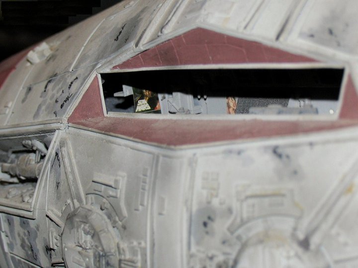
I also opened up the bridge in preparation for a miniature command center to be installed:

FS0lLFE.jpg

Finally, I cleared out space in the main hull for a battery pack:

xd9UBzT.jpg

I'm going to have to find one that will fit.

More progress as I get to it.

I want to do this so badly. But I don't. Because the whole idea is terrifying. And I haven't done all that much wiring in my life. Still. So frickin cool.

Post some videos of it in a dark room some time.

and I can barely paint.... lol. so want to be able to do this.

I cringed at the first picture. My corvette was scheduled to be here today, but will end up arriving tomorrow, and just...I want it so badly, then I see one destroyed like that and oh, the pain...
But, I know it's going to be fantastic when completed. Definitely looking forward to seeing the finished product

Brave man cracking that thing open. Remember to put up a pinup photo and a star wars poster at the back of the command bridge

6670666.jpeg

antilles-poster.jpg

Edited by Rob Jedi

Impressive!

Great work looking forward to se the results!

Since I plan on tearing mine open as well, mind posting a few pictures of it disassembled and sharing a few tips on what you found easy/hard to break apart?

What sort of pics would you be interested in?

The easiest parts to break off were the engines. Just torque them around and the glue will eventually give way. The nozzles were easy, too. All I did was roll my eXacto along the seam and they popped right off. The hardest was getting the main hull halves apart. They would not budge! I had to snip the pins a few times. But they sides are not glued down. Just the caps on the hammerhead and the docking rings, as well as the greeble strips on the midships wedge.

Wow....just wow!!! $100 coverted to a pile of plastic pieces. I wish you the very best!!

Wow....just wow!!! $100 coverted to a pile of plastic pieces. I wish you the very best!!

I prefer to think of it as "in the shop". :P

Really, this isn't as difficult as it might first appear. The parts are merely superglued in place, and superglue is notoriously brittle. So all it takes is a little pressure for the components to come apart.

What sort of pics would you be interested in?

The easiest parts to break off were the engines. Just torque them around and the glue will eventually give way. The nozzles were easy, too. All I did was roll my eXacto along the seam and they popped right off. The hardest was getting the main hull halves apart. They would not budge! I had to snip the pins a few times. But they sides are not glued down. Just the caps on the hammerhead and the docking rings, as well as the greeble strips on the midships wedge.

The joints mainly. I see the seam splitting the top from the bottom, but i still don't really see all the seams for the engines.

Here's a good pic of the seams on the left side engines:

ldwqdHD.jpg

You can see them quite clearly here. Inside there are some pins holding the halves together, but they're easy enough to see when you pull the engines off. I didn't even open this area up, as there was plenty of room inside for wiring. The only pin that got in my way was the one right behind the square plug that fits in a socket on the main hull, and it was easily Dremeled away.

Anyway, I decided to start the next build session by drafting out a floorplan for the bridge, based on the Blueprints: Rebel Edition floorplan. It will look pretty snazzy when it's finished. Those "shadows" are areas on the floorplan that you won't be able to see through the window. I planned them out so I knew how much detail would be necessary. The white circles inside them are where I plan to place LEDs for lighting. Here it is reduced to 45% and set inside the hammerhead:

bxIYsMS.jpg

I'm saving that little project for later. First I want to finish the engines. But there was a little area that was all too tempting to work on. On the bottom of the hull there is a small panel that was perfect for a switch cover:

U4qydoz.jpg

I'm going to put a recharge socket for the internal battery in here. I was going to have the battery pack slide in and out of the docking ring area toward the back, but I couldn't thin the plastic enough to work, even for a small AAA battery pack. So I'm going to find a small rechargeable battery for phones and such and place it inside the hull, then simply connect it to a charger when it runs low.

Back to the engines, I decided to try a few combinations, but the very first one I tried happened to look perfect:

5erbvE2.jpg

It consisted of a red, yellow, and flame-circuit yellow trio with a warm white LED to the side. I had to separate the warm white LED because it draws too much power and so doesn't glow as brightly when hooked up in parallel to the other LEDs. The flame LEDs are from electronic tea light candles and came with self-contained integrated circuits inside their bodies, so it's easy to solder them in line with other LEDs to get a flickering engine glow. Looks great, doesn't it? Unfortunately I decided to forgo the white LED because a) it would require a more complex circuit and b) I only have three of them and I don't want to wait on a special order of warm white LEDs. They look okay even at this reduced brightness:

prs3dTX.jpg

I realized, I forgot to show you the running lights on the midships wedge:

IGaasrc.jpg

Anyway, after I tested the LED combination and found a suitable one, I got the requisite number of each color and type and soldered them together in little clusters:

RkL6tA5.jpg

When that was done I began to work on getting the engines ready for lights. On each engine I first took the engine body and lined the interior with self-adhesive foil strips to block light. Then I cut a small circle of clear acrylic and fit it to the inside of the engine, then sanded it to frost the surface. Then I took the engine nozzle and lined the sides on the inside with more foil. Finally I glued it all together:

9z48yqY.jpg

K70vXZJ.jpg

w2z6YIo.jpg

That's as far as I've gotten. I'm too tired right now to do more, so I'm going to go to bed and try and get some more done tomorrow.

Everyone who has purchased a CR90 is now looking at it in disgust. Incredible work.

This is SO NICE!

Very impressive.

I know what I would have done. I would have cut it up, much the same, bought the new super cool light stuff. Put on or two things together on it...

and abandon the project altogether, mostly through losing interest, and I'd be out a $75 model.

Good job keeping with it.

That looks so awesome

This. Looks. Amazing.

I don't approve of LEDs hooked up directly to a battery though - especially if they're set up in parallel!

Edited by Klutz

Looking really good so far!

I love it, it really temps me to do the same thing...

This. Looks. Amazing.

I don't approve of LEDs hooked up directly to a battery though - especially if they're set up in parallel!

Yeah, I would recommend getting the proper resistor(s) set up there. I didn't bother with my YT because it's such an easy thing to change everything out, and it doesn't have much extra space, but with this (and the GR-75) I fully plan on doing everything right... Battery holder, true switch, resistors, probably even secure the wiring by the LEDs so they don't fall out of place.

For the rest of the ship - are you using optics or just LEDs?

More pictures, OMG it is a beautiful thing to behold. I wouldn't have the guts to even begin what you are doing!

This. Looks. Amazing.

I don't approve of LEDs hooked up directly to a battery though - especially if they're set up in parallel!

Yeah, I would recommend getting the proper resistor(s) set up there. I didn't bother with my YT because it's such an easy thing to change everything out, and it doesn't have much extra space, but with this (and the GR-75) I fully plan on doing everything right... Battery holder, true switch, resistors, probably even secure the wiring by the LEDs so they don't fall out of place.

For the rest of the ship - are you using optics or just LEDs?

Don't worry, I'm just using a button cell for testing the lights. It has extremely low amperage, so it won't fry LEDs. It's designed to be hooked directly to the leads of an LED without destroying it. I'll be calculating the proper resistance using Ohm's Law when it comes time for that and then hook up the proper resistors to each circuit.

I'm using fiber optics for the running lights, because they're too small for the LEDs I have. I'll be hooking up some bright white LEDs to them so they'll illuminate the surrounding greebles.

Edited by Millennium Falsehood

Sweet. One of the things I came across as an issue with the MF was bleed through... both on the thin areas of plastic, and where it was taken apart. On the MF I ended up putting several coats of black paint on the inside of the hull to keep the bleed through from occurring, and a soft felt along the edges where the pieces joined to create a tighter seal between them.

Just something to keep in mind.

Aluminum tape is far superior. It's thin and easy to cover with. The only downside is worrying about short circuits (especially the kind that can cause your super-elite military robots to turn into hippies, but I digress), but if you use heat shrink tubing on your leads and double check for shorts before closing it up, like I do, then the risk is minimal.